An injection-molded part that won’t fill, won’t release, or won’t fit the press doesn’t fail on the factory floor — it fails on your screen, in the CAD model, weeks earlier. Three numbers tell you which way it’s going to go, and you can read all three before you spend a dollar on steel. Get them right and the rest of the DFM work is routine; get one wrong and you are paying — in tooling rework, scrapped shots, schedule — to mold a problem you could have caught in ten minutes.
1. Wall thickness — and its uniformity
Every resin has a comfortable nominal wall: a thickness it fills, packs, and cools cleanly. ABS and PC are happy around 2.0–3.0 mm; polypropylene likes 1.0–2.0 mm; unfilled nylon flows thin but warps, so 1.5–3.0 mm is sane; glass-filled grades are stiffer and less forgiving, so stay nearer 2.0–3.0 mm. Pick one nominal wall and design the whole shell around it.
But the headline number is not the wall itself — it is the ratio of thickest to thinnest section. Hold every feature within roughly ±20% of nominal. Plastic shrinks in proportion to how much material is there: a thick lump cools from the outside in, the skin freezes first, then the core contracts and pulls the surface down with it. On a show face that is a sink mark; buried in a thick section it is a void — a vacuum bubble where the resin tore itself apart cooling. Thin sections fail the other way: the melt freezes before it fills, and you get a short shot or a weak knit.
The fix for a heavy area is almost never “add material.” It is coring — hollowing the thick region so the remaining wall matches nominal — then restoring stiffness with ribs. Keep a rib at roughly 0.5–0.6× the wall thickness at its base; thicker and the rib telegraphs its own sink onto the opposite (usually cosmetic) face. Make ribs tall and thin, not short and fat — height buys stiffness, bulk buys sink.
Bosses — the posts that take screws and heat-set inserts — are the classic uniformity trap, because a solid post is a thick section by definition. Hollow the boss so its wall matches the part wall, hold it off the main wall with a thin web or a ring of small gussets, and never blend the boss base straight into the shell as one solid mass. A boss with no relief is just a thick spot wearing a useful shape, and it will sink exactly where you mounted your most visible screw.
A wall-ratio example you will actually hit
Say the shell wall is 1.5 mm and you need a screw boss with a 3.0 mm outer diameter. Drawn naively, the solid boss base is about 3.0 mm of plastic where it joins the wall — a 2:1 thick-to-thin ratio, double your ±20% budget. That junction cools last, contracts hardest, and pulls a visible dimple onto the outside surface directly behind the boss. The cure is geometric: bore the boss so its wall is about 1.5 mm, stand it on a thin web, and add three or four small gussets if it must resist a screw’s side load. Same function, same screw, no sink — because no section is meaningfully thicker than the 1.5 mm wall everything else honors.
2. Draft angle
A mold is two halves of steel that close, fill, and pull apart. Every face running along the direction of that pull has to taper, or the cooling, shrinking plastic grips the steel and refuses to let go. That taper is draft, and it is the difference between a part that drops out of the tool and one that scuffs, drags, or stays stuck until the ejectors punch dents into it.
The floor is 1° per side for smooth surfaces; 1.5°–2° is more comfortable and costs almost nothing in the model. Deep ribs and tall walls want more draft, because more surface area grips the core. Textured faces need substantially more: roughly 1.5° of extra draft for every 0.025 mm of texture depth. A coarse leather or matte grain — the Mold-Tech grades you specify by number — can demand 3°–5° or more, because the part has to slide up out of every peak and valley etched into the steel. Specify the texture and the draft together; a grain quoted without enough draft galls the finish on the first ejection, and you re-cut the tool.
Watch the shut-offs too — where the two mold halves touch to form a hole or opening. Steel meeting steel at a shallow angle makes a fragile knife-edge that chips under clamp load and flashes within a few thousand shots; aim for at least 3°. Zero-draft anywhere is the most expensive “free” choice on the part: it forces extra ejectors, slower cycles, hand-polishing along the pull, and sometimes a full redesign of the face once the first shots come back marked.
3. Projected area × cavity pressure → clamp tonnage
When the cavity fills, the melt pushes outward on both mold halves and tries to blow them apart at the parting line. The press has to clamp harder than that push, or you get flash — a fin of plastic squeezed into the gap. The opening force is simply the projected area of the part (its shadow along the direction of pull, including runners) times the cavity pressure the resin needs to fill and pack. Converted to tons, that product is your minimum clamp tonnage — and clamp tonnage is exactly how presses are sized and priced.
Cavity pressures vary by resin and wall: an easy-flowing, thick-walled ABS part packs at 200–350 bar, while a thin-walled, long-flow part in a stiff glass-filled grade can demand 700 bar or more. Guess optimistically and your part does not fit the press you budgeted; you bump up a machine size or two, and both the tooling and the per-shot rate climb with it.
A worked tonnage estimate
Take a part with a projected area of 150 cm² molded in ABS that packs at roughly 350 bar, and work it in consistent units. 350 bar is 35 MPa = 35 N/mm²; the projected area is 150 cm² = 15,000 mm².
- Separating force = 35 N/mm² × 15,000 mm² = 525,000 N ≈ 525 kN.
- Convert to tonnes-force: 525,000 N ÷ 9,810 N/tonne ≈ 53.5 tonnes.
- Add a safety margin of about 10–20% for runners, packing spikes, and a worn parting line → roughly 60–64 tonnes.
Round up to a standard press: this part lives comfortably on an 80-tonne machine, with headroom. Had you assumed 700 bar instead — a thin-wall or glass-filled case — the same area would need about 107 tonnes before margin and push you onto a 150-tonne press, with the cost to match. The arithmetic is trivial; skipping it is what gets expensive, because nobody discovers the part is on the wrong machine until the quotes come back high or the first run flashes.
Why these three first
Wall, draft, and tonnage are upstream of everything else. If they are healthy, the rest of the DFM list — gates, runners, cooling, ejection — is solvable engineering a competent toolmaker handles every day. If any one is wrong, no gate location or cooling layout can rescue the part. The sections below are the next tier: real decisions that shape cost and quality — but only once the three numbers are sound.
Gate type and location
The gate is where melt enters the cavity, and where it enters dictates how the part fills, where seams land, and what scar it leaves. Every gate leaves a mark, so put it on a hidden face, never on a Class-A surface. Where two flow fronts meet they form a weld line (knit line): a visible, structurally weaker seam. You steer weld lines by gate position — keep them off show faces and out of load paths. If a cosmetic face matters, decide the gate before the tool is cut, not after you see the seam.
Gate type trades cost against finish. An edge gate is cheap and robust but leaves a nub you trim. A sub-gate (tunnel gate) shears off automatically on ejection, hiding the scar but adding tool complexity. A hot tip eliminates runner waste and leaves a tidy mark, at meaningfully higher tooling cost. None is “best” in the abstract — it is a finish-versus-cost call you make per part.
Parting line and ejector marks
The parting line is the seam where the two mold halves meet; it runs around the whole part whether you planned it or not. Choose it deliberately so it falls on an edge or a natural break, because there will always be a faint witness line there, and a sliver of flash as the tool ages. Ejector pins push the part off the core and leave small circular marks; they belong on interior or hidden surfaces, on robust features that take the push without distorting. If you have not told the toolmaker where the parting line and ejectors should go, the tool decides for you — and it rarely decides in favor of your cosmetic face.
Uniform cooling and cycle time
You pay for plastic parts largely by the second, and the mold spends most of each cycle waiting for the part to cool enough to eject without distorting. The thickest section sets that clock: cooling time scales with the square of wall thickness, so a 3 mm wall cools about four times slower than a 1.5 mm wall. Every thick lump you leave in lengthens every cycle for the life of the tool. Uniform walls also cool evenly — less internal stress, less warp; uneven walls cool at different rates and bow the part. Good cooling-channel layout helps, but it cannot fully fix geometry that insists on cooling unevenly.
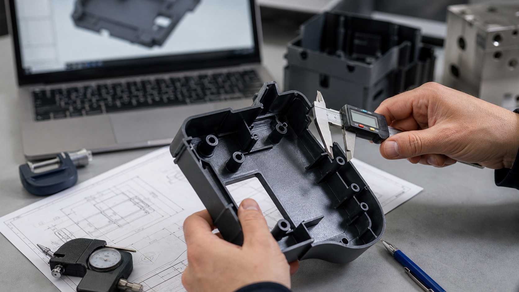
Tolerances the process can actually hold
Injection molding is a high-volume process, not a precision-machining one, and it will not hold machined tolerances. A realistic general tolerance for a molded feature is on the order of ±0.1–0.2 mm for small features, looser as the dimension grows, and looser still across a parting line where two tool halves stack up. Milled aluminum or turned metal holds ±0.025 mm all day; plastic cannot, because the part is shrinking by a percentage as it cools and that shrinkage is never perfectly uniform. Tighten only what truly needs it — a bearing seat, a snap-fit engagement, a sealing face — and let the rest run at general tolerance. A drawing covered in tight callouts the process can’t meet just tells the molder you don’t know the process, and invites a caveated quote or a stack of out-of-spec first articles.
Material shrinkage
Every resin shrinks as it solidifies, and the toolmaker cuts the steel oversize to compensate — so the shrink rate is baked into the tool. Change resins after the mold is cut and your dimensions move. The spread is large enough to matter.
| Resin | Typical nominal wall | Typical mold shrinkage | Minimum draft (smooth) |
|---|---|---|---|
| ABS | 1.5–3.0 mm | ≈0.4–0.7% | 1°–1.5° |
| PC | 2.0–3.0 mm | ≈0.5–0.7% | 1°–1.5° |
| PP | 1.0–2.0 mm | ≈1.5–2.0% | 1°–2° |
| Nylon (PA, unfilled) | 1.5–3.0 mm | ≈1.0–2.0% | 1°–2° |
| POM (acetal) | 1.5–3.0 mm | ≈1.8–2.5% | 1°–2° |
| Glass-filled (e.g. PA-GF, PBT-GF) | 2.0–3.0 mm | ≈0.2–0.8% (anisotropic) | 1.5°–2°+ |
Notice the range: unfilled ABS shrinks around 0.5%, while POM shrinks closer to 2% — four times as much. On a 100 mm dimension that is the difference between losing 0.5 mm and losing 2 mm, and the tool is cut for exactly one of those. Glass fill complicates it further: the part shrinks less along the fibers than across them, so it can warp even with uniform walls. Lock your resin before you cut steel, and treat any later material change as a tooling change — because it is.
Undercuts and side-actions
An undercut is any feature that hooks behind the line of pull — a side hole, a snap-fit lip, a recessed logo, a latch — so the part can’t simply lift off the core. Every undercut needs a moving piece of steel to clear it: a slider (side-action) that retracts sideways as the tool opens, or a lifter that angles inward during ejection. They work, and they are everywhere in real products — but each adds tooling cost and moving parts that wear, can slow the cycle, and often leaves its own witness line.
The cheapest undercut is the one you design out. Before committing to a slider, ask whether a shut-off can do the job — passing the side hole straight through against a feature on the opposing mold half, so the hole forms in the direction of pull with no moving steel at all. Often a small geometry change converts a side-action into a free pass-through. When the undercut is genuinely needed, count the sliders and lifters early: they are a direct line item, and a tool with four side-actions costs and maintains very differently from a clean two-plate mold.
Common mistakes and failure modes
- Uneven walls. A nominal 1.5 mm shell with random 3 mm lumps — sink on the show face, voids inside, warp from uneven cooling, and a slower cycle forever.
- No draft on textured faces. A grain quoted without the extra draft it needs galls the finish on the first ejection. You re-cut the tool.
- Knife-edges at shut-offs. Steel feathered to a fragile edge chips under clamp load and flashes within a few thousand shots.
- A boss thicker than the wall. Solid posts are thick sections in disguise; they sink exactly behind your most visible screw. Core them and web them.
- Trapping air. A deep blind rib or pocket with no path for air to escape burns the resin at the far end (diesel effect) — a scorched, short-filled corner. The tool needs venting; the design should not fight it.
- Tolerances the process can’t hold. A drawing of ±0.02 mm callouts on a molded part yields a caveated quote or out-of-spec first articles. Tighten only what must be tight.
- Changing resin after the tool is cut. Shrink is built into the steel; swapping ABS for POM moves every dimension and can scrap the tool.
A pre-quote checklist
Before you send a part out for a mold quote, walk it once against this list. Ten minutes here saves weeks downstream.
- One nominal wall chosen for the resin, with every feature inside ±20% of it. Heavy areas cored, not bulked.
- Ribs at 0.5–0.6× wall, tall rather than fat; bosses hollowed and webbed off the wall.
- Draft on every face along the pull — at least 1° smooth, more for depth, and texture-matched draft (≈1.5° per 0.025 mm) wherever you’ve called out a grain.
- A tonnage estimate done: projected area × cavity pressure, converted to tonnes, plus margin, rounded to a real press size.
- Gate and parting line placed with intent — off cosmetic faces, weld lines steered away from show surfaces and load paths.
- Tight tolerances limited to the few features that need them; everything else at general molding tolerance.
- Resin locked (and its shrink known) before steel is cut.
- Undercuts counted — each slider and lifter acknowledged as cost, and designed out via shut-offs wherever possible.
Read wall-uniformity, draft, and projected-area tonnage off the model before you quote tooling — they predict most of the DFM pain for the cost of ten minutes, and everything else is solvable once those three are sound.