The cheapest part on the BOM, and the easiest to ruin
A PCB antenna costs nothing — it’s copper you were going to etch anyway. A chip antenna is a few cents. Yet the antenna is the single component most often destroyed not by a bad part choice but by the geometry around it: a ground pour that crept too close, a battery sitting where the fields want to be, a shield can three millimetres away. You almost never catch it in schematic review, because the schematic is fine. You catch it weeks later, in the radiated-test report, when total radiated power (TRP) comes back 5 dB low and the lab politely notes that your radiated efficiency is “approximately 18%.” That number is your range, your battery life on the link budget, and sometimes your certification, all at once — decided by where you put the copper.
Antenna types and what each one demands of the layout
Three families cover almost everything a hardware team ships. They differ less in performance than in how much real estate they reserve and how unforgiving they are about it.
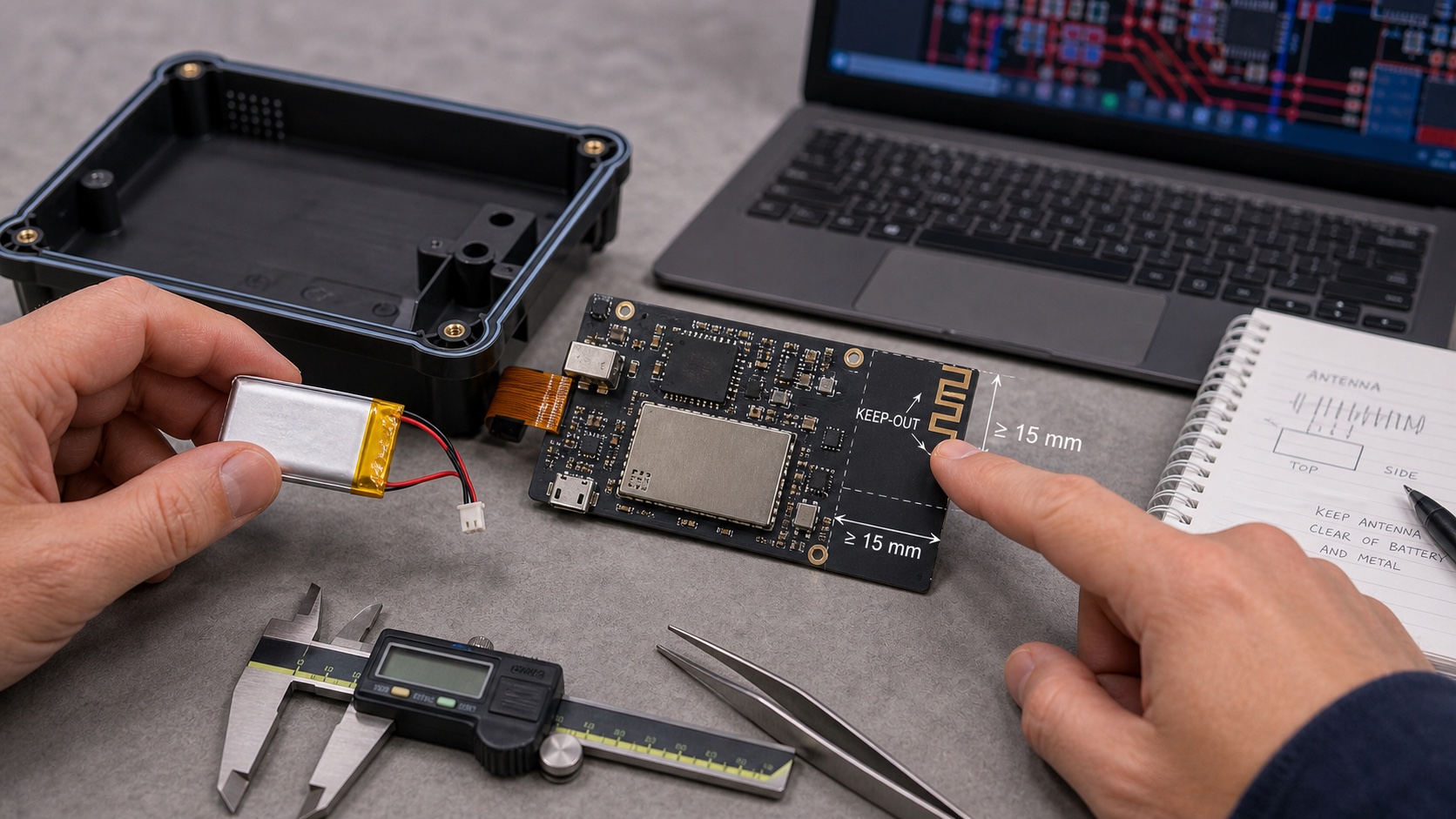
- PCB trace antennas (IFA, meander, inverted-F). Etched directly into the board. Free in unit cost, but they pay rent in area: an inverted-F at 2.4 GHz is roughly 12–16 mm long and wants a clear region around it — typically 5–10 mm of nothing on the same layer and a matching cut-out in every other copper layer beneath. They are the most sensitive to anything you place nearby, because the radiating element is exposed copper with the whole world coupling into it.
- Chip / ceramic antennas (LTCC, multilayer). A surface-mount part, 3–7 mm long. The vendor hands you a reference layout and a keep-out polygon. The chip is small, but the keep-out is not: it still needs a ground-clear zone of similar size to a trace antenna because the ground plane is doing half the radiating. People assume “it’s a component, I’ll treat it like one” — and then drop a 0402 right inside the forbidden zone.
- FPC, external whip, or connectorised antennas. A flexible printed antenna on a polyimide tail, or a whip on a U.FL/SMA connector. These move the radiator off the crowded board entirely — up a wall, into a lid, away from the battery. That is their whole point. The penalty is cost (connector, cable, assembly labour) and a coax run whose routing and grounding you now have to get right.
The ground plane is part of the antenna
This is the idea that, once internalised, prevents most antenna disasters. A quarter-wave-class antenna on a small board is not a self-contained radiator sitting on an inert surface. The ground plane is the counterpoise — the other half of the dipole. The element pushes current, and the ground plane carries the return; together they radiate. Shrink, slot, or crowd that ground and you have changed the antenna itself, not merely its surroundings.
Two consequences follow. First, the keep-out / clearance zone — the region the datasheet marks as “no copper, no parts, no ground” — is not a courtesy margin. It is where the near fields live. Put copper there and you are loading the antenna with capacitance it wasn’t designed for, pulling its resonance off-band and dumping energy into the plane as heat instead of into the air. Second, the antenna actually wants a decent ground plane adjacent to it to work against. Tiny boards (think a coin-cell tracker) are hard precisely because there isn’t enough ground to serve as counterpoise, and efficiency suffers no matter how clean the keep-out is.
Do not shrink the reference-design keep-out. The vendor characterised the part on that exact geometry. When the mechanical engineer asks for “just 2 mm back” to fit a boss, understand that you are not trimming whitespace — you are detuning a tuned circuit and you will pay for it in the chamber. If the keep-out genuinely does not fit, that is a signal to change antenna type (go to an FPC, move it to a lid), not to quietly violate it.
Plastic versus metal: the proximity that detunes and shorts
Plastic is mostly transparent to RF but not free. A plastic wall a millimetre off the antenna has a dielectric constant around 2–3 and will lower the resonant frequency — it “loads” the antenna. That is exactly why you tune with the plastic in place (next section). The shift is real but predictable, and you can design for it.
Metal is the enemy. Anything conductive near the antenna does one of two ugly things: it detunes by coupling capacitively, or, close enough, it effectively shorts the near field and craters efficiency. The usual offenders, ranked by how often they wreck a design:
- The battery. A LiPo pouch or 18650 is a large grounded metal slab, and it is heavy and hard to move late. An antenna laid over or beside the cell with a millimetre of gap can lose 6–10 dB. Keep the cell out of the keep-out entirely; treat 5 mm as a floor and more as better.
- Shield cans. The grounded can over your RF or PMIC section is metal too. Its wall must respect the keep-out like any other ground.
- USB / connector shells, screws, springs, metal stiffeners. The grounded USB shell sitting next to a corner antenna is a classic 3 dB thief. Decorative chrome rings and metallised paint count as well.
- The user’s hand and head. Tissue is lossy, high-permittivity, and shows up only when someone holds the product the way people actually hold it. A wearable that tests beautifully on the bench can lose several dB the instant a wrist wraps around it. If the use case involves a hand, characterise it with a phantom or at least a hand on the unit — do not let the field report be your first hand test.
Where the antenna wants to live on a crowded board
The antenna has preferences, and they conflict with everyone else’s. Give it priority, because it is the only part on the board that talks to the outside world through geometry.
- A corner or a short edge. Edges radiate; the middle of a board is surrounded by ground and parts. The vendor reference layout almost always puts the element at a board edge, fed from the corner, for exactly this reason.
- Far from the switchers. A buck converter is a tiny broadband transmitter. Sit a sensitive receive antenna next to its switch node and you raise your noise floor — worse total isotropic sensitivity (TIS), even with perfect efficiency. Put physical distance and ground between them.
- Away from the display and its flex. An LCD/OLED and especially its FPC are noisy metal sheets. Antennas hate living under or beside a display flex; route the flex away and keep the antenna on the opposite edge.
- Matching network within a few millimetres. The pi-network (typically three places: series, shunt, shunt) must sit right at the feed, on a clean 50 Ω line. Every extra millimetre of trace before the match adds parasitic reactance that the match then has to fight, and short stubs at GHz frequencies are not negligible. Reserve the room next to the feed for those three parts on day one.
The matching network, and why you tune after the plastic is on
Between the radio and the antenna sits a small pi matching network — usually three pads for 0402 L/C parts — whose job is to transform the antenna’s impedance back to 50 Ω so the radio delivers its power instead of reflecting it. You populate it after measuring the assembled product on a vector network analyser, picking component values to drive return loss deep (S11 well below −10 dB) across the band.
The trap: the antenna’s impedance depends on everything around it — the plastic housing, the battery, the metal, the hand. Tune on a bare PCB and the match is correct for a board that will never ship. Snap the enclosure on and the dielectric loading shifts resonance, your carefully tuned S11 walks off the band, and efficiency drops. Always tune in the final mechanical configuration: real housing, real battery, real internal metal, lid closed. If the product is held, the realistic answer is to find a compromise match that survives both free-space and hand-loaded cases, because you can’t retune in the field.
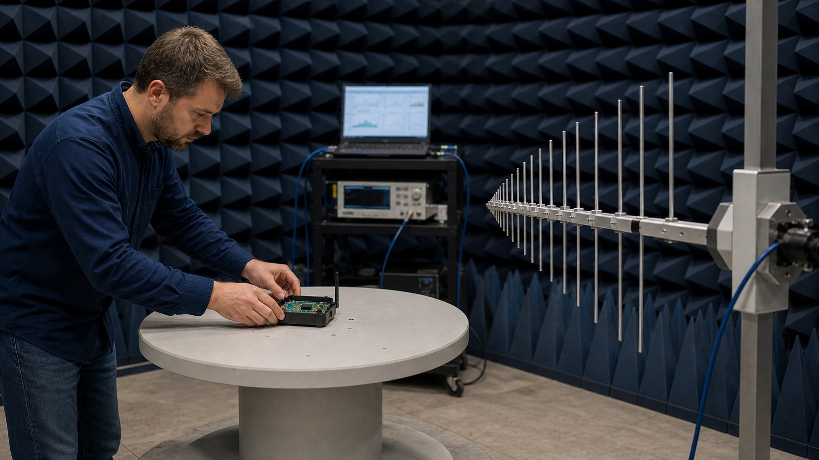
What the radiated test actually measures
In the chamber, the lab is not reading S11 off your bench — that only tells you power got into the antenna, not that it left the building. They measure what radiates, integrated over a sphere:
- Radiated efficiency (%) — of the power delivered to the antenna, the fraction that actually leaves as radiation rather than turning into heat in nearby metal, lossy plastic, or the match. This is the headline number a violated keep-out destroys.
- TRP (total radiated power) — for transmit. Your radio’s conducted output power minus all the losses, summed over every direction. A weak TRP means short range and, near regulatory edges, a failed emissions limit either way.
- TIS (total isotropic sensitivity) — for receive. How faint a signal you can still hear, averaged over the sphere. Hurt by the same geometry losses plus any self-generated noise from those switchers you placed too close.
Worked numbers: length, and the price of a violated keep-out
First, the size you’re committing to. A quarter-wave element at 2.4 GHz:
λ/4 = c / f / 4 = (3×10⁴ m/s) / (2.4×10⁹ Hz) / 4 = 0.125 m / 4 ≈ 0.03125 m = 31 mm.
That 31 mm is the free-space figure; meandering, dielectric loading, and the ground plane pull the physical copper shorter (often 12–16 mm for an IFA), but it tells you the order of magnitude of real estate this radiator wants. There is no shrinking it to 8 mm and expecting 2.4 GHz.
Now the cost of getting the geometry wrong. Say a clean reference design gives 60% efficiency, and your violated keep-out — ground pour crept under the element, battery 1 mm away — drops it to 25%. The loss in dB:
10 × log₁₀(0.25 / 0.60) = 10 × log₁₀(0.4167) = 10 × (−0.380) ≈ −3.8 dB.
That is the radiated power you threw away with layout alone. Because range in free space scales with the square root of received power, losing half your power (−3 dB) costs you about 30% of your range; −3.8 dB is worse still, and on the receive side TIS degrades by the same margin, so the link suffers at both ends. Two of these mistakes stacked — battery proximity and a shrunk keep-out, say −7 dB — and you have an 80% power loss and a product that “works on my desk” and nowhere else.
Common mistakes and failure modes
- Shrinking the keep-out to fit the layout. The most common and most expensive. The vendor’s keep-out is a measured boundary, not a suggestion. “Just 2 mm” is several dB.
- Ground pour under the antenna. The autorouter or a careless copper pour fills the keep-out on an inner or bottom layer because nobody told it not to. Lock a keep-out region into every layer in the CAD tool.
- Antenna against the battery, a shield can, or the USB shell. Late mechanical packing shoves metal into the one zone that had to stay empty. Reserve the antenna’s volume in the 3D model before the battery is placed.
- No room for the matching network. The feed line runs 15 mm to find space for three 0402s. Place the pi-network pads at the feed on the first layout pass.
- Tuning on a bare board, then adding plastic. The match is perfect for a configuration that ships to nobody. Tune in the final enclosure, with the battery, lid closed.
- Ignoring the hand. Bench numbers look great; the product is worn or gripped in real life. Test hand-loaded if a hand is ever involved.
- Treating S11 as the finish line. A deep return loss only proves power entered the antenna. It can still be radiating that power into a nearby shield can as heat. Efficiency, not S11, is the truth.
Quick reference: type, keep-out, ground relationship
| Antenna type | Typical keep-out | Ground relationship | Watch out for |
|---|---|---|---|
| PCB trace / IFA | ~5–10 mm clear, all layers | Ground plane is the counterpoise; needs ground adjacent, none under the element | Inner-layer pour creeping in; tiny boards lacking counterpoise |
| Chip / ceramic | Vendor polygon, often 5–8 mm; do not shrink | Ground-clear zone under and around; works against adjacent ground | Dropping parts inside the keep-out because “it’s just a component” |
| FPC / flex | Per datasheet on the flex tail; route away from metal | Often needs a defined ground at the feed; grounding scheme matters | Folding it against a battery or metal bracket in assembly |
| External whip / connectorised | Mechanical clearance + clean coax run | Self-contained radiator; ground via connector / cable | Coax routing and connector grounding; cost and labour |
Treat that keep-out as a hard mechanical reservation with the same authority as a screw boss — lock it in the 3D model, defend it in every layout and DFM review, and tune the match in the final closed enclosure. Geometry is free to change only until the tool is cut and the first article hits the chamber; after that, the test report is just an invoice for the millimetres you gave away.
The antenna is the cheapest part on the BOM and the easiest to wreck with geometry — protect the keep-out, keep metal and the ground pour out of it, and tune with the plastic on, or the test report will read your efficiency back to you in dB.